NoICE Debugger

ARM Tutorials

Running NoICE for the first time

Connecting to hardware

Compiling for debugging

Source-level debugging

 
Home Download Purchase Tutorials FAQ NoICE Help

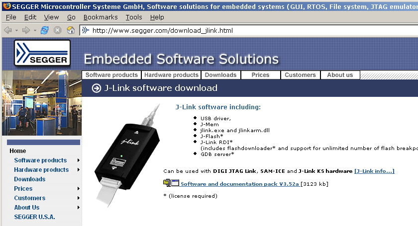
Connecting to Hardware Using Segger JLink

In the section of the tutorial, we will show how to connect and configure the Segger JLink JTAG pod for use with an LPC2106 target. Our target board is the Olimex LPC-P2106-B.

Click here for a tutorial on connecting to hardware using OpenOCD (supports various JTAG pods, including the Macraigor Wiggler, Olimex ARM-USB-OCD, Amontec JTAG key, Signalyer, etc.)

Click here for a tutorial on connecting to hardware using H-JTAG (supports the Macraigor Wiggler and clones)

If you haven't done so already, we recommend that you go through Running NoICE for the first time before reading this section of the tutorial.

Installing Segger JLink Driver Software

Segger (https://www.segger.com) sells a JTAG pod called the J-Link and various associated software. The J-Link is also sold by IAR under their own bright yellow label and included in IAR demo kits; and by Atmel as the bright blue SAM-ICE. NoICE will work with the Segger, IAR, or Atmel versions of the J-Link.

Before plugging in the JLink or running NoICE, you must install the JLink drivers. If you installed the IAR or Atmel software, you may already have the necessary drivers installed. Otherwise, you can get the latest drivers and support software from Segger at https://www.segger.com/download_jlink.html. (The actual version you see may differ from this snapshot).

Downloading Segger JLink software

Install the Segger software.

Downloading Segger JLink software

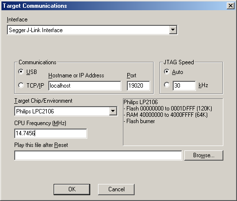
Connecting the Segger JLink JTAG Pod

  1. Turn off power to the target.

  2. Verify any jumper and switch settings on your target board. On the Olimex LPC-P2106, do not install the BSL (serial bootloader) jumper; do install the DEBUG (DBGSEL active) jumper; do not install the JRST (reset by RS-232 DTR) jumper. For other target boards, consult your board's documentation.

  3. Connect the pod to the JTAG connector on your target. Be sure to orient the connector correctly, or damage to the pod or the target board may result. In many cases, the cable and the connector will be keyed so that only one orientation is possible.

    Pin 1 on the JTAG cable is almost always indicated by a red stripe on the edge of the cable.

    Pin 1 of the JTAG connector on the target board is often indicated by a "1" on the silk-screen. If not, look on the back of the board. Pin 1 is often indicated by a square pad.

  4. Connect the USB cable from the JLink to your PC. If the driver was properly installed, you should hear the usual Windows "ding-dong".

  5. Turn on power to the target.

  6. Run NoICE.

  7. Select "Target Communications" from the "Options" menu, then select "Segger J-Link Interface" from the "Interface" drop-list.
    Segger JLink setup dialog


    • Select "USB" as the communications method. The Segger software also supports a remote connection via TCP/IP, but a USB connection to your PC is simpler and much more common.

    • Select JTAG speed "Auto".

    • Select your Target Chip: "Philips LPC2106" in this example.

    • Set the CPU frequency to match the target. The Olimex board has an 14.7456 MHz crystal, so the CPU frequency is 14.7456 MHz.

    • For now, leave "Play this file after Reset" blank.

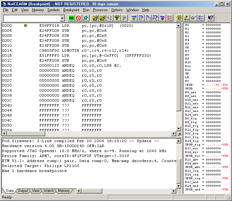
Press "OK" in the Target Communications dialog, and NoICE will show an initial display like that shown below. If you exit NoICE and come back in, you will return right here. Initial NoICE display using JLink

In this case, memory contains a previously-burned program. Since the ARM begins execution at address 0, that is where PC starts out. NoICE disassembles from the PC.

At this point, you may wish to repeat the simulator examples on real hardware.


The next step is to burn a program into Flash. This example uses ImageCraft ICCARM, as described in the previous section of the tutorial, Compiling for Source-level Debugging.

You can follow along even if you don't have this compiler. All files necessary for you to run the NoICE demo may be downloaded here: hellofoo.zip. Setup for other compilers is generally similar.

Run NoICE. Select "File", "Load...".

By default, you will see hex files such as hellofoo.s19. You could load that, but all you would get would be disassembly, as the s19 file doesn't contain any symbolic debug information.

So change the "Files of type" to"ImageCraft DBG files".

Navigate to hellofoo.dbg and press "OK".

NoICE help on LOAD

Load dialog for ImageCraft DBG files

When you Load the file into the Flash range, a progress dialog appears: It shows the address being burned and the progress of the burn.

Once burning is completed, you can continue with the source-level debugging example


NoICE help

NoICE help on ARM


NoICE Debugger • Copyright © 2019 by John Hartman • Revised 11 October 2019