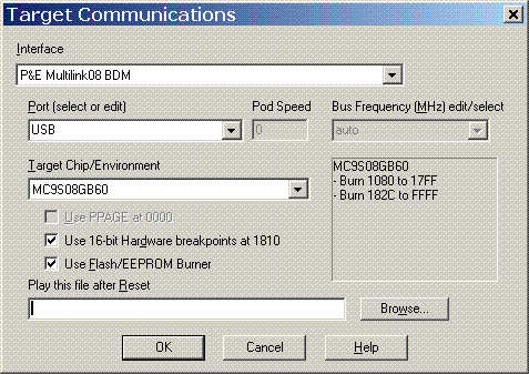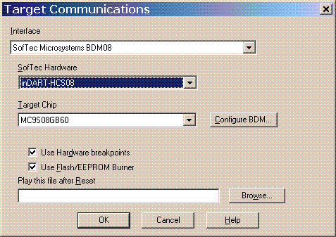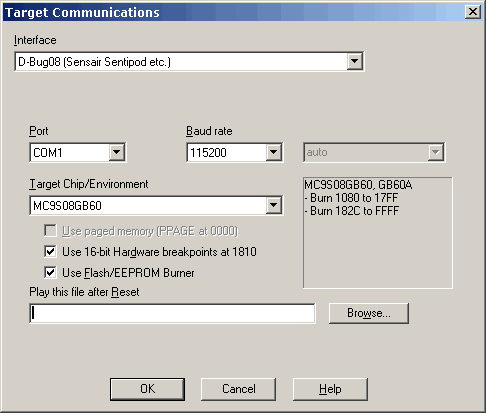
Click on a field for more information about its function.
The Motorola/Freescale MC9S08 includes a feature called Background Debug Mode, or BDM. Some of their documentation calls this a "Background Debug Controller" or BDC. NoICE documentation will refer to it as BDM. Most MC9S08 evaluation boards and single board computers include a BDM port, usually using a 6-pin connector.
NoICE support for BDM is contained in an optional DLL (NComBDM.dll). Some BDM pods also require the installation of a vendor-provided driver. Currently supported are
Additional pods may be supported in the future. Contact us if you need support for a particular pod not listed here.
More information is available on
Before you can use NoICE with your BDM pod, you may need to install the appropriate driver.
If your pod uses a serial interface such as D-BugS08, no driver is required besides the standard Windows serial driver.
For other pods, you should install the driver that came with the pod, or visit the vendor's web site to get the most recent driver. This is especially true if you are running Windows Vista, which tends to hate any driver older than a week and a half...
Follow the manufacturer's instructions for connecting and using your pod. In most cases, you will need to proceed in this order:
Once you have set up the BDM pod, you will not need to repeat the last four steps on subsequent runs.
To disconnect the BDM pod from the target, you will need to
Failure to follow the manufacturer's instructions for connecting and disconnecting may result in damage to the BDM pod or to your target.
This section describes the common items in the BDM configuration dialogs. Pod-specific information may be found below.
Use the Target Chip/Environment list to select your target processor. Please be careful to select the exact chip that you are using. Use of the incorrect algorithm may damage the chip. If you can't find an appropriate type, please contact the Author. "Generic MC9S08" is safe in all cases, but will not allow you to burn Flash or use hardware breakpoints.
Once you select a target, the Hardware Breakpoint and Use Flash Burner checkboxes will be enabled if the selected target supports these features.
The Bus Frequency (MHz) combo box specifies the target bus frequency. This is one half of the crystal frequency. With some pods, this field will be grayed out and show "auto", meaning that the pod will automatically determine the frequency that the target is running at.

Select the appropriate port from the Port combo box. If you are using the USB Multilink, select "USB". Otherwise, select the parallel port to which your BDM is connected. The BDM interface actually uses port addresses rather than LPTn numbers, so the addresses traditionally used by parallel ports are shown. When in doubt, go with the address, not the LPT number.
If you are unsure of the address of your parallel port, run the Windows Control Panel. Double-click on "System", and select the "Device Manager" tab. Expand the item labeled "Ports (COM and LPT)". Select your port, and press the "Properties" button. Select the "Resources" tab. The "Input/Output Range" specifies your port's address.
If your parallel port's address doesn't match one of the selections in the Port list, you can enter the port's address in hex. NoICE will accept only addresses in the range 0x200 to 0xFFFF. Please be careful: addressing something other than a parallel port may cause your PC to do surprising (and generally undesirable) things!
If you are running Windows XP and find that you have trouble the first time you run NoICE after booting, but that things work thereafter, please read about disabling Windows port polling
The Pod Speed box shows a speed value used by the BDM pod. When you press "OK" in the dialog, NoICE will determine the proper setting of the speed, and store it in the Registry. This process may take several seconds, so please be patient. On subsequent runs, NoICE will use the setting from the Registry for faster initialization.
If you use a firewall, you may receive a warning when you run NoICE for the first time after selecting a P&E pod. For example, the Windows XP Firewall says
"Windows Firewall has blocked this program from accepting connections from the Internet or a network."
This is because the P&E BDM DLL supports all P&E BDM pods including an Ethernet version (Cyclone). The DLL runs an enumeration process that listens on a TCP port. Since NoICE does not support the Cyclone pod, you can tell your firewall to block access to the port. This should have no effect on NoICE.
Please read additional information about configuration

Select the appropriate hardware device from the SofTec Hardware drop list.
Press Configure BDM... to open a dialog box that controls various settings for the SofTec BDM pod.
Use the Target Chip/Environment list to select your target processor.
Please read additional information about configuration
NoICE uses the BDMDB commands.
Before using your D-BugS08 pod with NoICE, verify that it works correctly in pod mode with your target. Follow the instructions that come with the pod.
Once pod mode works, use your terminal program and the BAUD command to set the baud rate to be used with NoICE. Typically, this should be 38,400 or faster. The pod stores the baud rate in EEPOM, so you only need to perform this step once.
Exit the terminal program and run NoICE. Select an available serial port from the Port drop list. Select the correct baud rate for your pod from the Baud rate drop list.

Please read additional information about configuration
"Classic" NoICE assumes that the program you are debugging is in RAM. This permits NoICE to easily download the program, and to set an unlimited number of breakpoints by writing bgnd or swi instructions.
However, providing enough RAM to hold the program is always a problem. Writing to Flash memory is much more complex than writing to RAM, and it is usually not possible to change the value of a single byte without erasing a larger area. Thus, the "classic" model won't work for debugging programs in Flash.
Most of the MCS908 family include three hardware breakpoints which NoICE can use instead of bgnd/swi instructions during debugging. This leaves only the problem of getting the program to be debugged into Flash.
NoICE includes code licensed from Elektronikladen that can burn Flash for many members of the MC9S08 family.
The MC9S08 family has a security feature controlled by the contents of the NVOPT register, located in Flash memory at address 0xFFBF. NoICE always programs this byte to the value 0x7E. This disables security. If you attempt to burn a file that differs from this, you will get a Flash verify failure. The alternative would be to let you program the bits, and then have BDM be disabled the next time you reset the chip.
Flash burner operation is as follows
If you need to burn more than one Motorola/Freescale hex file to make a complete program image, please read about EatS9.
Most MC9S08 parts can use either a crystal/resonator, or an internal oscillator as the source of processor clock. While using a crystal or resonator results in the best accuracy, using the internal oscillator offers lower cost and saves pins.
When the internal oscillator is to be used, it will usually be calibrated on the production line, and the calibration value saved in Flash memory. Your startup code must copy the saved value to the oscillator trim register during initialization of the clock subsystem. NoICE's configuration information for each chip includes the addresses of the trim register (ICGTRM, MCGTRM or ICSTRM, depending on the chip) and the location in Flash where Freescale recommends storing the calibration value (called TRIM or NVTRIM in many datasheets).
During Flash burning, NoICE will preserve the value of the calibration byte(s), unless the file being burned specifies a value for that byte or bytes, or unless NoICE has been used to calibrate the oscillator.
At least some MC9S08 parts are shipped with a trim value already present in Flash. If this value is somehow erased, or if you want to use a different the frequency, select "Tune/Trim Bus Frequency..." from the "Processor" menu. NoICE will compare the target speed to the PC clock. Accuracy may be limited in some cases by the communications overhead of the BDM pod.
Some MC9S08 parts, including the QDxx, QGxx, and Dxx lines, come out of reset with the tunable clock enabled. These may be trimmed immediately.
On other MC9S08 parts, including the AWxx, GBxx, and GTxx, the ICG must be enabled after reset before the tunable clock may be used. You can do this by hand, using NoICE's memory modification commands, but it is probably easiest to use a command file. The NoICE\config directory contains the file MC9S08_ICG_trim.noi which shows one way to initialize the ICG:
	Echo Enable ICG (as on MC9S08AWxx, GBxx, or GTxx) for trimmable clock
	; Parts with MCG (DNxx, DVxx, DZxx) do not need initialization before trimming
	; Parts with ICS (QDxx, QGxx) do not need initialization before trimming
	;
	; These settings are only one possible option.
	; Change as necessary to match your desired configuration.

	; ICGC1: REFS=1 (crystal osc. enabled); CLKS=01 (FLL enabled)
	out 0x48 0x28

	; ICGC2: MFD=011 (times 10); RFD=001 (divide by 2)
	out 0x49 0x30
To tune the clock
Once you have tuned the clock and burned the NVTRIM value, this value will be preserved on subsequent LOAD/burns.
.NoICE with BDM08 allows an advanced feature called "Virtual UART". This allows the target to use the BDM port to communicate with the Output Window as with a dumb terminal.
Characters in the range 0 to 255 decimal are allowed, and will be displayed using the current Windows character set.
If keyboard focus is in the Output window and the user presses any key other than a function or cursor key while the target is executing, the ASCII/Windows representation of the key will be sent to the target via the serial port.
The Virtual UART requires two consecutive dedicated RAM locations, one for output, and one for input. Both the target and NoICE/BDM read and write the memory locations to implement a communications channel.
To begin using the Virtual UART, the target must clear both memory locations to zero. Whenever the target is running, NoICE polls both bytes.
In order to send a byte to the Output Window, the target simply writes to the first, "output", memory byte. When NoICE sees a non-zero value in the output byte, it displays that value in the Output Window, and then clears the output byte. The target must not write to the output byte unless it is zero, or characters will be lost.
When the user presses a key while the focus is in the Output Window, NoICE will write the key value to the second, "input", memory byte. When the target sees a non-zero value in the input byte, it returns that value as if from a UART, and clears the input byte. NoICE will not write a keyhit to the input byte unless it is zero.
To define the memory locations to be used, edit the BDM configuration file noice08_targets.ini in the NoICE\config directory. For the MC9S08GB60, for example, there is text:
    [MC9S08GB60]
    partID=0x18060002
    DBG16=0x1810
    ramstart=0x0080
    start=0x1080
    last=0x17FF
    start1a=0x182C
    last1a=0xFFFF
    multifrequencyBurner=1
    toolfile=tf2_s08gx60_flash.bin
    remarks=MC9S08GB60
The memory locations to be used must not be used by your program for any other purpose. This may require you to change your linker file to avoid these bytes, or to define them in your program, as shown below.
The GB60 has RAM from 0x80 to 0x107F. To define a Virtual UART at address 0x1000, we insert the line
virtualUART_address=0x1000
into the ini file. It is a good idea to copy the section and give it a name that shows what you are doing. This can prevent confusion later, should you have another BG60 project on which you don't want to use the Virtual UART. In our example, we add
    [MC9S08GB60 with Virtual UART at 0x1000]

    partID=0x18060002
    DBG16=0x1810
    ramstart=0x0080
    start=0x1080
    last=0x17FF
    start1a=0x182C
    last1a=0xFFFF
    multifrequencyBurner=1
    toolfile=tf2_s08gx60_flash.bin
    remarks=MC9S08GB60
    virtualUART_address=0x1000

    remarks=Any MC9S08GB60 with Virtual UART at address x01000
The target code required to use the Virtual UART is similar to any polled UART code. The major difference is that instead of testing a status bit in a status register, the target tests the zero/non-zero value of an entire byte.
Here is an example, done using ImageCraft ICC08 showing how to declare and initialize the Virtual UART
    /* Location MUST match NoICE configuration */
    #pragma abs_address 0x1000
    char VUART_TX, VUART_RX;
    #pragma end_abs_address

    void main(void)
    {
       /* Initialize the Virtual UART */
       VUART_TX = 0;
       VUART_RX = 0;

       etc.
    }
To connect the Virtual UART to printf, you must replace ImageCraft's putchar function with this:
    int putchar (char c)
    {
       if (c == '\n')
          putchar('\r');

       while (VUART_TX != 0)
       {
       }

       VUART_TX = c;
       return c;
    }
CAUTION: if you run your program without NoICE, this version of putchar will hang after sending the first byte, since NoICE won't clear VUART_TX. The solution is usually to use a different version of putchar for release versus debug.
To use the Virtual UART for input, you must replace ImageCraft's getchar function with this:
    int getchar (void)
    {
       int retval;
       while (VUART_RX != 0)
       {
       }

       retval = VUART_RX;
       VUART_RX = 0;
       return retval;
    }
Assembly code is similar:
    VUART_TX equ $1000
    VUART_RX equ $1001

    ; During init:
       CLR     VUART_TX
       CLR     VUART_RX
       (etc)

    ; Usage
    PUTCHAR:
        TST     VUART_TX
        BNE     PUTCHAR
        STAA    VUART_TX
        RTS

    GETCHAR:
        LDAA    VUART_RX
        BEQ     GETCHAR
        RTS
Whenever you press "OK" in the Target Communications dialog for a P&E pod, NoICE attempts to determine the speed of the target. This may take several seconds. Once the speed has been determined, it is stored in the registry for future use. Normally, this should be transparent to you. However, if you have problems communicating with your target, it may be worth opening the Target Communications dialog, verifying all the settings, and pressing "OK" to get the pod to check communications speed.