First a disclaimer: during the first ten years that we sold NoICE, we received many requests for target processor simulation. We resisted providing one, feeling that most embedded processors are used to control specialized external hardware, which is often difficult or impossible to simulate exactly.
Instruction set simulation is quite straightforward. However, simulating the UARTs, timers, and other peripherals found on current microprocessors is a very complex task - at least if you want a good (i.e., useful) simulation. The cycle-by-cycle operation of these peripherals is seldom publicly documented, and anything less than a cycle-by-cycle simulation will mask problems which occur in real systems.
That said, the customer has spoken, and the customer wants a simulator. So, NoICE provides instruction simulators for ARM7, MSP430, 68HC12, 68HC08, and 8051. Simulators for other target architectures will be released as demand dictates and development time allows.
Here's what you get
Here's what you don't get
In summary, NoICE simulates instruction execution. It does not simulate a competent and thoughtfull programmer. Just because a program "works" on the simulator is no guarantee that it will work on read hardware.
Real targets usually have a mix of RAM, Flash, EEPROM, ROM and I/O at various addresses.Some have unimplemented addresses that cause an interrupt if read or written. NoICE does not simulate the exact memory layout of the target processor. Instead, you get 64K of uniform RAM
NoICE supports the standard instruction set for each simulated target, However, there are a few instructions that cannot be simulated accurately.
The NoICE simulated UART provided just enough functionality to act as a polled UART. This is useful in that it allows your code to use printf, puts, getchar, putchar and the like to interact with a simply TTY window.
If, while the simulated target is executing, it writes a character to the simulated UART's transmit data register, that character will be displayed in the NoICE Output Window as if on a dumb terminal. The only control characters supported are carriage return (0D hex), line feed (0A hex), tab (09 hex), bell (07 hex), and backspace (08 hex). All other characters will be displayed using the current Windows character set. The entire range 0 to 255 is allowed.
A "transmit ready" status bit is provided for compatibility with standard polled UART code. However, the bit will always be set, regardless of how fast data is written to the transmit data register. As we keep saying, this is not a cycle-accurate simulation of a UART.
If keyboard focus is in the Output window and the user presses any key other than a function or cursor key while the target is executing, the ASCII representation of the key will appear in the simulated UART's receive data register, and the "receive ready" bit will be set in the simulated UART's receive status register. When the simulated target program reads the receive data register, the receive ready bit will be cleared.
The simulated UART does not require or pay attention to UART initialization code. Code that works with the simulated UART is not guaranteed to work with a real UART.
The simulated UART does not generate interrupts.
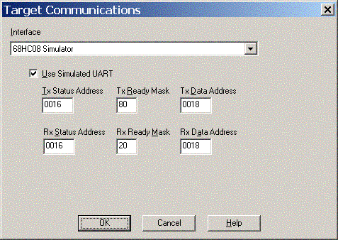
Before using the simulated UART, you must configure it. In most cases, you will wish to set the parameters to match a UART on your physical target processor. This will allow you to use any standard library implementations of printf and the like provided by your compiler vendor.
Consider this example from the datasheet for the 68HC08GP32

This UART (called an SCI by Motorola/Freescale) has a status register called SCS1 at address 0x0016. Bit 7 (called SCTE, for SCI Transmitter Empty) is set when the UART transmit register is ready to accept an output byte. Bit 5 (called SCRF, for SCI Receive Full) is set when the UART receive register contains an input byte.
This UART has a data register called SCDR at address 0x0018. Bytes written to this register are transmitted by the UART. When read, this register returns the last byte received by the UART.
Using this data, we configure NoICE's simulated UART:

Note that in this case the Tx and Rx Status Addresses are the same, as are the Tx and Rx Data Addresses. This is common for many, but not all, UARTs, In particular, the MSP430 UARTs use different addresses for Tx and Rx Data.
Today's microprocessors contain elaborate timer subsystems, CAN and USB interfaces and other peripherals whose complexity may exceed that of the processor itself. NoICE makes no attempt to simulate such devices.
You can, however, use NoICE's WATCH capability to allow convenient monitoring of values written to and read from any address. For example, The 68HC08 has an 8-bit I/O port at address 0x0000. We can use the commands
    DEFINE PORTA 0
    WATCH PORTA %B08
to define a watch on memory address zero. The "%B08" tells NoICE to display the value as 8 binary bits. If omitted, the value would be shown as a hex byte.
To change the value, just double-click on it in the Watch window.
In order to watch the same set of ports each time you run NoICE, create a NoICE command file containing the DEFINE and WATCH commands. Then make the command file be your Startup file.